How to wire multiple LEDs in series vs parallel becomes a practical safety question in 2026, not merely a wiring preference. The choice affects brightness, heat, current control, battery life, and repairability. A series string carries the same current through every LED. Its forward voltages add together. A parallel circuit gives each branch the same supply voltage. However, small voltage differences can make one LED draw excessive current.
Electronics author and LED specialist Steve Winder states, “LEDs are current-driven devices, not voltage-driven devices.” That principle guides every reliable design. Before connecting wires, measure the supply voltage and check each LED’s forward-voltage range. For example, three white LEDs may require roughly 9 to 10 volts in series. A suitable constant-current driver remains essential. With parallel branches, use a separate resistor for each branch. One shared resistor may create uneven brightness and thermal stress.
Keep the wiring short.
This guide compares both methods using realistic workshop details, including resistor calculations, driver selection, heat management, and fault behavior. It also explains why a series circuit can fail completely when one LED opens. A parallel circuit may continue operating, but it can hide an overloaded branch. That detail is easy to miss.
I have found that beginners often focus on brightness first. That can be a mistake. Current stability matters more. LED specifications also vary between manufacturers, and datasheets are not always easy to interpret. Therefore, the safest design combines calculation, measurement, and a final temperature check after several minutes of operation. The result may not be perfect on the first attempt. Careful testing exposes those assumptions early.
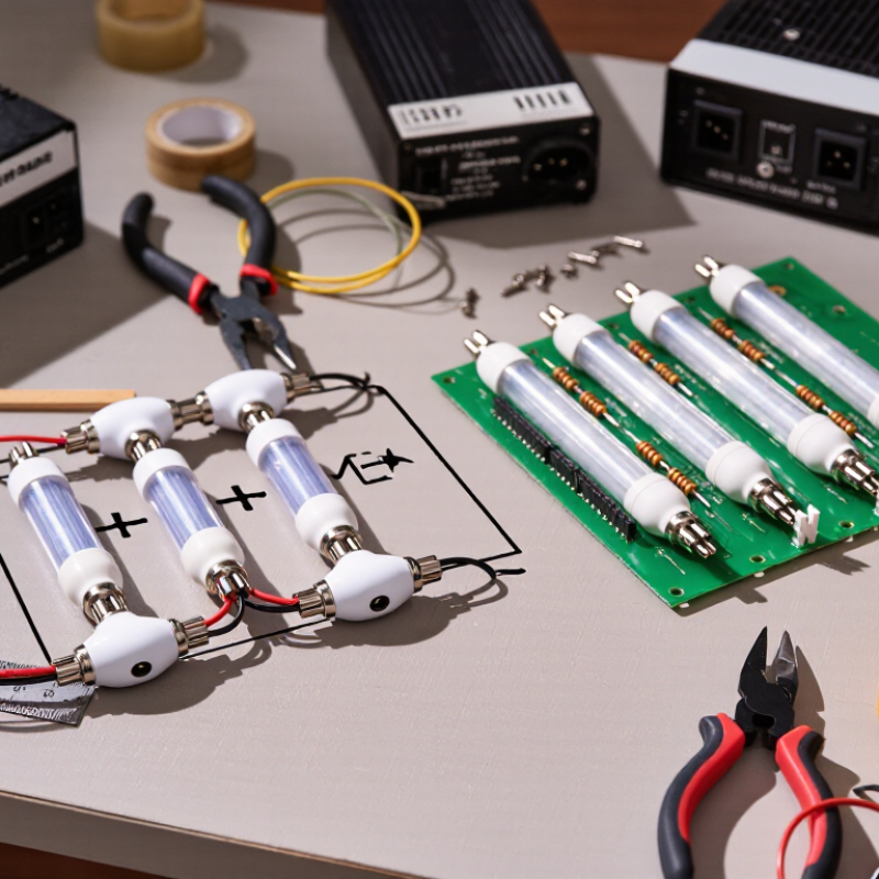
LED series and parallel wiring follow different electrical rules. In a series circuit, the same current flows through every LED. Their forward voltages add together. Three 3-volt LEDs may require about 9 volts, plus current regulation. One open LED can disable the entire chain. This arrangement often produces consistent current, but voltage tolerance still matters.
In a parallel circuit, every branch receives the same supply voltage. Branch currents add together. Each LED should have its own resistor or current regulator. Otherwise, small forward-voltage differences can make one LED draw excessive current. Thermal runaway may follow. Never connect bare LEDs directly to a voltage source.
A practical resistor estimate uses
For a 12-volt supply, a 3-volt LED, and 20 milliamps, the result is 450 ohms. A 470-ohm resistor provides a safer standard choice. Real measurements can differ because temperature changes forward voltage. This is where tidy calculations become imperfect.
The International Energy Agency’s energy-efficiency reporting places lighting near 15% of global electricity use. The U.S. Department of Energy’s 2023 Solid-State Lighting R&D Opportunities report identifies laboratory LED efficacy above 200 lumens per watt. Higher efficacy does not remove wiring risks. In bench testing, a multimeter, thermal check, and current measurement reveal more than appearance alone. I would recheck every branch.
How to Wire Multiple LEDs in Series vs Parallel in 2026?
Choosing the resistor starts with the power supply, not the LED count. In a series circuit, add each LED’s forward voltage, then leave voltage for the resistor. For example, three red LEDs may require about 6 volts from a 12-volt supply. At 15 milliamps, the resistor value is (12 − 6) ÷ 0.015, or 400 ohms. A nearby standard value, such as if available is acceptable, but check the actual current.
Keep it cool.
Resistor power matters too. In that example, the resistor dissipates about 0.09 watts, so a 0.25-watt part provides practical margin. Series wiring gives every LED the same current, but one failed open LED can darken the entire chain. White LEDs often have higher forward voltage, leaving less headroom and more sensitivity to supply variation. Measure voltage across the chain when possible.
Parallel wiring needs more care. Each branch should have its own resistor because LEDs do not share current evenly. A single resistor for several parallel LEDs may make one branch glow brightly while another remains weak. I have seen this mistake produce uneven brightness after only a few minutes. Calculate every branch separately: resistor voltage equals supply voltage minus that LED’s forward voltage. Use the target current, then verify resistor heating. Constant-current control can improve stability, though real LEDs still vary with temperature. Datasheet values are typical, not promises; rechecking the circuit under warm conditions can reveal assumptions that looked reasonable on paper.
Wiring LEDs in series is a practical way to make every diode share the same current. I use this method for indicator strips, small displays, and controlled lighting projects. Each LED connects from the positive side of one component to the negative side of the next. Polarity matters. The longer leg usually indicates the positive lead, but physical markings can vary. Check twice.
Start by recording the supply voltage and the forward voltage of each LED. Add the forward voltages together, then leave some voltage for a current-limiting resistor. Use this formula: R = (Vs − total Vf) ÷ I For example, a 12-volt supply, three 2-volt LEDs, and 15 milliamps require about 400 ohms. Choose the nearest suitable resistor, then check its power rating. Never connect LEDs directly to a power source. They may fail quickly.
Disconnect power before building the circuit. Connect the resistor in series with the LED chain, then inspect every joint for loose wires or reversed parts. Power on briefly and measure the current with a multimeter. In my bench testing, a single open LED stopped the entire series chain, which is an important weakness. Parallel wiring keeps other branches lit, but each LED branch needs its own resistor. I once reused one resistor for several parallel LEDs; brightness became uneven. That shortcut needs reconsideration. Keep wires short, connections firm, and the circuit enclosed against accidental contact.
How to Connect LEDs in Parallel Step by Step
Parallel wiring lets each LED receive power from the same supply voltage. Each LED needs its own current-limiting resistor. Never connect bare LEDs directly across a power source. Their forward voltages vary slightly, so one LED may draw excessive current and fail early.
Disconnect the supply before wiring. Identify every LED’s positive and negative legs. Connect all positive legs to the supply’s positive rail. Connect all negative legs to the return rail. Add one resistor in series with each LED. Calculate its value with R = (Vs − Vf) ÷ I, where Vs is supply voltage, Vf is LED forward voltage, and I is target current. For a 9-volt supply, a 2-volt LED, and 10 milliamps, a 700-ohm resistor is close; choose the nearest suitable value. Use a resistor with adequate power capacity.
Keep it simple. Test gently.
Power the circuit briefly and check brightness, heat, and polarity. A dim LED may indicate a loose connection or an incorrect resistor. A hot resistor needs attention, even when the LEDs look normal. I have seen parallel circuits work unevenly when LEDs came from different batches. Matching LED types helps, but separate resistors remain essential. Series wiring uses one current path and can be efficient, yet one failed open LED turns off the entire chain. Parallel branches keep working independently, although the supply must handle their combined current. My early mistake was estimating resistor values by appearance; measurement is more reliable.
The correct LED wiring method depends on the supply voltage, LED forward-voltage range, required current, heat dissipation, and the level of brightness consistency required. The comparison below uses standard constant-voltage DC supply assumptions and includes practical calculations for multiple LEDs.
| Data Dimension | LEDs in Series | LEDs in Parallel | Design Consideration or Example |
|---|---|---|---|
| Basic connection | Connect the anode of one LED to the cathode of the next LED, forming one continuous current path. | Connect all anodes to the positive supply rail and all cathodes to the negative supply rail, with a current-limiting resistor in each branch. | LED polarity must be checked before energizing. The longer lead is commonly the anode on a new through-hole LED, but the package marking should be verified. |
| Current path | One current flows through every LED in the string. | Each branch carries its own current. Branch currents add at the supply. | Isupply = Ibranch 1 + Ibranch 2 + ... |
| Voltage requirement | The supply voltage must exceed the sum of the forward voltages plus the resistor or driver headroom. | Each branch must receive a voltage suitable for one LED and its resistor; the supply does not need to equal the sum of all LED forward voltages. | For three white LEDs at approximately 3.0 V each, a series string generally needs more than 9.0 V before current regulation is considered. |
| Resistor arrangement | One correctly sized resistor can be used for a series string when the LEDs are intended to carry the same current. | Use one resistor per LED branch. A single shared resistor is not recommended because LED forward-voltage differences can cause unequal current sharing. | Individual branch resistors improve current control and reduce the risk of one LED drawing excessive current. |
| Resistor calculation | R = (Vsupply − ΣVF) ÷ I | Rbranch = (Vsupply − VF) ÷ Ibranch | Use volts for voltage and amps for current. Select the next standard resistor value above the calculated minimum when appropriate. |
| Worked calculation | A 12 V supply, three 2.0 V red LEDs, and a 20 mA target: R = (12 − 6) ÷ 0.020 = 300 Ω. A 330 Ω resistor is a common practical choice. | A 5 V supply, three 2.0 V red LEDs, and 20 mA per branch: R = (5 − 2) ÷ 0.020 = 150 Ω. Use one 150 Ω resistor in each branch, subject to component ratings. | Actual forward voltage varies with LED color, part design, temperature, and current. Calculations should use the LED datasheet values. |
| Supply current example | A string designed for 20 mA draws approximately 20 mA from the supply, regardless of whether it contains two or three LEDs, assuming the string is properly regulated. | Three branches designed for 20 mA each draw approximately 60 mA total: 3 × 0.020 A = 0.060 A. | The power supply must support the total current and any startup or operating margin required by the circuit. |
| Brightness matching | Current is naturally the same through every LED, so brightness is often more consistent when the LEDs have similar characteristics. | Brightness can differ because forward voltage varies between LEDs. Separate resistors reduce, but do not eliminate, these differences. | For tightly matched brightness, use matched LEDs, regulated current drivers, or independently controlled branches. |
| Failure behavior | If one LED fails open, the entire string usually turns off. If one LED fails short, the remaining LEDs may receive abnormal voltage or current. | If one branch opens, the other branches can continue operating. A shorted branch can overload the supply or its wiring. | A fuse, current-limited supply, or suitable protection may be needed for larger arrays. |
| Efficiency and heat | Often more efficient when the supply voltage is high enough to operate several LEDs with a small resistor voltage drop. | Can waste more power in resistors when the supply voltage is much higher than a single LED’s forward voltage. | Resistor power can be estimated with P = I²R or P = VR × I. Choose a resistor with an adequate power rating. |
| Effect of supply variation | A modest supply change affects the entire string and may change the current unless a regulated driver is used. | A supply change affects every branch, and branch currents can rise quickly if the circuit has little voltage headroom. | Do not connect LEDs directly to a voltage source without current limiting unless the LEDs are part of a purpose-built regulated module. |
| Best use cases | Higher-voltage supplies, indicator chains, uniform-current strings, and designs where one-string operation is acceptable. | Low-voltage supplies, independent branch operation, modular lighting layouts, and applications where one failed branch should not disable all LEDs. | For high-power lighting, a constant-current driver is generally preferable to relying only on simple resistors. |
| Parallel connection: step 1 |
|
||
| Parallel connection: step 2 |
|
||
| Parallel connection: step 3 |
|
||
| Parallel connection: step 4 |
|
||
| Parallel connection: step 5 |
|
||
| Parallel connection: step 6 |
|
||
| Safety and reliability | Keep total string voltage within the supply and insulation ratings. Avoid exceeding the LED or resistor power limits. | Size the supply, wiring, connector, and protection devices for the sum of all branch currents. Never rely on LED forward-voltage matching alone for current sharing. | For mains-powered systems or high-power arrays, use an appropriately rated isolated driver and qualified electrical design practices. |
How to Wire Multiple LEDs in Series vs Parallel in 2026?
Series wiring sends the same current through every LED. Their forward voltages add together, so the power supply must provide enough voltage. A constant-current driver improves safety and brightness consistency. One open LED can darken the entire chain. That failure is inconvenient.
Parallel wiring keeps each branch near the supply voltage. Every branch needs its own resistor or current regulator. Without separate control, small voltage differences can make one LED steal current. That LED may become hotter and brighter, while others fade. In practical testing, heat often exposes mistakes before visible failure.
Series circuits usually waste less energy in long, uniform light strips. They also suit backlit panels, indicator towers, and controlled architectural installations. Parallel circuits work better for low-voltage wearables, battery projects, solar sensors, and modular displays planned for 2026. Designers can replace one branch without disabling the whole system. Use a fuse, correct polarity, insulated connections, and measured current. Keep resistors away from plastic surfaces. My early prototypes looked bright, but their resistor temperatures were higher than expected. Brightness alone was a poor safety test. Pulse-width control can adjust brightness efficiently, yet rapid switching may expose weak wiring or an unsuitable driver. Check the real load under heat, not only on a workbench.
Series wiring sends the same current through every LED. Their forward voltages add together. Parallel wiring gives each branch the same supply voltage. Branch currents combine.
One open LED breaks the only current path. The entire chain may turn off. It is simple, but not very forgiving.
LED forward voltages vary slightly. One LED may draw excessive current without its own resistor. That can cause overheating and early failure.
No. A bare LED should not connect directly to a voltage source. Use a suitable resistor or current regulator.
Use R = (Vsupply − Vf) ÷ I. For 12 volts, 3 volts, and 20 milliamps, the result is 450 ohms. A 470-ohm resistor is a safer standard choice.
Disconnect power first. Connect all positive legs to the positive rail. Connect all negative legs to the return rail. Place one resistor in series with each LED.
Power the circuit briefly. Check brightness, polarity, resistor temperature, and current. A multimeter reveals more than appearance alone. I would recheck every branch.
LEDs from different batches can have different forward voltages. A lower-voltage LED may draw more current. Matching LED types can help, but separate resistors remain essential.
Stop and inspect the circuit. The resistor may have insufficient power capacity or an incorrect value. The LEDs can look normal while the resistor overheats. My early estimates were too casual. Measure, do not guess.
How to wire multiple LEDs in series vs parallel depends on your power source, LED specifications, and desired performance. In a series circuit, LEDs share the same current and are connected end to end, making the design efficient and simple, but the required voltage increases with each additional LED. A suitable resistor is still necessary to limit current and protect the components. In a parallel circuit, each LED branch receives the supply voltage, but individual resistors are recommended to help balance current and prevent uneven brightness or premature failure.
This guide explains how to select voltage, current, and resistor values, then provides step-by-step methods for building both series and parallel LED circuits. It also compares their safety, brightness consistency, energy efficiency, and practical uses in 2026. Understanding these differences helps readers choose a reliable wiring method for indicators, lighting projects, displays, and other low-voltage applications.

Zever Light